Wheather you’re a student, professional, or hobbyist, you will eventually come across SPICE Software when desigining electronics projects. SPICE software, such as LTspice, can be used to simulate your analog and digital designs without having to bust out a breadboard or soldering iron.
One of LTspice’s features I have found incredibly useful is it’s ability to process .wav files as a voltage input and the write the voltage output of the circuit to a new audo file.
Audio Settings
When working with audio in LTspice, it is important to ensure the correct audio format and encoding are used. The .wav file is just a container for uncompressed pulse-code modulation (PCM) data.
To process audio files in the .wav file format it is important to make sure the file is encoded corectly. The .wav file is a just a container for raw uncompressed pulse-code modulation (PCM) data.
So when importing your audio files into LTspice make sure you take note of the audio encoding, bit rate, sample rate, audio duration and make sure the audio channel is monophonic
Most audio recording software has the option to export wavefiles in 8-bit to 32-bit PCM format. In most cases, 16-bit should suffice.
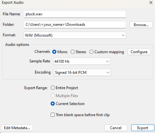
See Audacity Export Example
Download Audacity or Audacity github
Open a new Audacity project and navigate to Tracks > Add New > Mono Track. Click on the newly added track and then navigate to Generate > Pluck to make a guitar plucking sound.
Take note that Audacity uses the MIDI pitch number which is diffrent than the key number when generating the pluck sound.
LTspice Settings and Circuit
Once you have your audio file you want to use, I would recommend moveing it into the root directory where your LTspice project is located. Otherwise, you will have to provide the full path to your audio file.
.
├── pluck.wav
└── project.asc
Add Audio Input
Right click the value of your voltage source and put the folowing in the empty text box.
wavefile=path/to/your_audio.wav
This voltage source will now serve as your audio input in your circuit.
Simulation settings
The next step is going to be to set up a transient analysis equal to the duration of your audio sample.
This can be done by adding the flowing directive by pressing . on your keyboard. You can also use the GUI by naviagiting to Simulate > Configure Analysis and edit your settings in the Transient tab.
In my case my directive looks like the flowing but you may need to change the duration of analysis.
.tran 0 1s 0s 0.1s
Audio Output
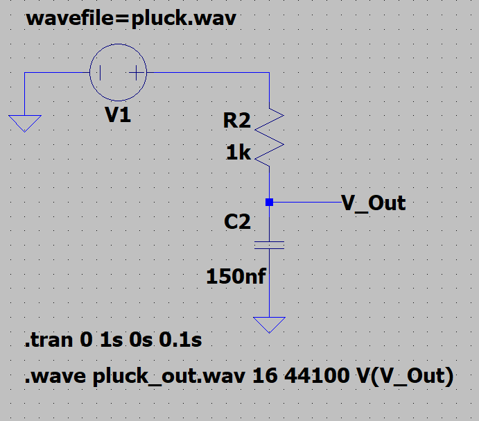
The next step is going to be to add the output newtork lable by pressing n on your keyboard. Keep note of the name of this node as it acts as a varable for the output data. In the example image this is V_Out.
See Example Low Pass Filter Schmatic
click here if you want to know more about RC filters
Here is a simple low pass filter example with a cut off frequency of $ \approx 10061 $ Hz which is the closest I could get using standard components.
Remember
$$ f_c = {1 \over 2\pi RC} $$
Once you have your circuits input, output, and simulation settings configured we need to use the .wave directive to output your audio file the circuit.
.wave <output.wav> <bit rate> <sample rate> V(<output node>)
Given my audio settings.
.wave pluck_out.wav 16 44100 V(V_Out)
Example Audio
Listen carefully, the original audio should sound sharper than the outputted file. Looking at LTspice output image (right) you can see the attenuation from the right of the red line onward compared to the original audio (left).
| Original | LTspice output |
|---|---|
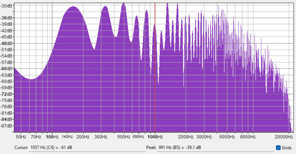 | 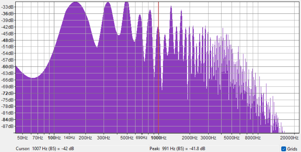 |